Design and produce something with a digital process (incorporating computer-aided design and manufacturing) not covered in another assignment, documenting the requirements that your assignment meets, and including everything necessary to reproduce it.
Table of Contents
Hero Shot
Week 15 Work Plan
Idea
🚨
The idea for my soft robotic gripper for this week is illustrated below.
Inspiration
💡
Robots have captivated my attention since my earliest years. I was five years old the first time I saw a robot with my father. It was a huge robotic manipulator, and I was restricted from entering. I observed with curiosity. I hadn't asked anyone about it at the time, and I wasn't even aware of its name. It stayed in my mind. Now, soft robotics is another area that interests me. Mr. Praveen Kumar's soft robotic gripper motivated me to experiment with soft robotics this week.
Soft Robotics
Soft robotics is a subfield of robotics focused on creating robots constructed from highly flexible materials, often inspired by biological systems. Unlike traditional rigid robots made of metals and hard plastics, soft robots are designed using materials like silicone, rubber, and other polymers, which allow for more natural, adaptable, and safe interactions with their environment.
⬇️
Follow the link below to learn more about soft robotics.
Material Composition: Soft robots are primarily made from soft, flexible materials that can deform and adapt to their surroundings. Common materials include silicone, rubber, and various polymers.
💠
Actuation Methods: These robots often use unconventional actuation methods such as pneumatics (air pressure), hydraulics (fluid pressure), shape-memory alloys, and electroactive polymers to achieve movement and control.
💠
Biomimicry: Soft robots frequently mimic biological organisms (e.g., octopuses, worms, and human muscles) to achieve fluid, lifelike movements and functions that are difficult for traditional robots.
💠
Safety and Compliance: Due to their flexibility, soft robots are inherently safer for interaction with humans and delicate objects. They can absorb shocks and adapt to unstructured environments without causing damage.
Applications of Soft Robotics
💠
Medical and Surgical: Soft robots can be used in minimally invasive surgeries, prosthetics, and rehabilitation devices, offering gentle and precise interaction with human tissues.
💠
Search and Rescue: Their adaptability and ability to navigate through confined spaces make them suitable for search and rescue operations in complex and hazardous environments.
💠
Manufacturing and Automation: Soft grippers and manipulators can handle delicate objects and perform tasks that require a gentle touch, such as in food processing and electronics assembly.
💠
Wearable Devices: Soft exoskeletons and assistive devices can enhance human movement and provide support for individuals with mobility impairments.
💠
Exploration: Soft robots can be used in environments that are difficult for traditional robots to navigate, such as underwater or in space, due to their ability to withstand harsh conditions and deform to fit through tight spaces.
Challenges in Soft Robotics
💠
Control and Sensing: Developing precise control systems and integrating sensors into soft robots is challenging due to their deformable nature.
💠
Durability: Ensuring the longevity and robustness of soft robots under repeated stress and deformation is a key concern.
💠
Fabrication: Creating soft robots involves complex manufacturing processes to produce and integrate soft materials with the required properties.
Soft Robotic Gripper
A soft robotic gripper is a type of end-effector designed for robots, characterized by its flexible and adaptive grasping abilities. Unlike traditional rigid grippers, which are made from hard materials and operate with fixed motions, soft robotic grippers are constructed from pliable materials such as silicone, rubber, and other polymers. This enables them to conform to the shape of the object they are handling, providing a gentle and secure grip.
Key Features of Soft Robotic Grippers
💠
Flexibility and Adaptability: Soft grippers can adapt their shape to grasp objects of various sizes, shapes, and textures. This makes them highly versatile for handling irregular or delicate items.
💠
Safety: The soft materials reduce the risk of damaging objects or causing injury during human-robot interaction. This is particularly important in applications involving fragile or sensitive items.
💠
Bio-Inspired Designs: Many soft grippers are inspired by biological structures such as the tentacles of an octopus or the human hand, which are capable of intricate and adaptable movements.
Actuation Methods
💠
Pneumatics: Air pressure is used to inflate and deflate chambers within the gripper, causing it to open and close. This method provides smooth and precise control over the gripping force.
💠
Hydraulics: Fluid pressure is used similarly to pneumatics but typically provides more force, suitable for handling heavier objects.
💠
Shape-Memory Alloys (SMA): These materials change shape in response to temperature changes, allowing the gripper to open and close when heated or cooled.
💠
Electroactive Polymers (EAP): These materials deform when an electric field is applied, enabling the gripper to change shape and grasp objects.
Applications of Soft Robotic Grippers
💠
Manufacturing and Automation: Used in assembly lines for picking and placing items of different shapes and sizes without needing multiple grippers or manual adjustments.
💠
Food Processing: Capable of handling delicate food items like fruits and vegetables without causing bruising or damage.
💠
Medical and Surgical: Employed in robotic surgery and handling medical instruments or tissues, where precision and gentle manipulation are crucial.
💠
Agriculture: Utilized for harvesting crops, where the ability to adapt to different shapes and the delicate nature of the produce are essential.
💠
Consumer Products: Integrated into household robots for tasks such as picking up toys, handling laundry, or other domestic chores.
Challenges and Considerations
💠
Control Systems: Developing precise and responsive control algorithms for soft grippers is complex due to their deformable nature.
💠
Material Durability: Ensuring that the soft materials used can withstand repeated use and harsh environments without degrading.
💠
Sensing and Feedback: Incorporating sensors that can provide real-time feedback on grip strength and object position to enhance control and adaptability.
My initial step in designing the mold was to draw a rough idea on pieces of paper and try to visualize a 3D model of the soft robotic part. However, after designing, I made a few minor changes.
🚨
The soft robotic part is divided into two parts. The upper part has all the chambers and air pathways, and the second part is to seal the chambers and air paths of the soft robotic upper part.
🚨
To create the upper part, I need a two-part mold, and another mold for the second part.
🚨
I selected XY plane and started to draw a new sketch on that plane.
🚨
The complete design consists of three parts: the upper mold, the middle mold, and the bottom mold. The upper and middle mold are used for casting the top part of the soft robot, and the bottom part is used to cast the bottom part of the soft robot.
🚨
The image below illustrates a single view of the top part of the mold.
🚨
The image below illustrates a multi-view of the top part of the mold.
🚨
The image below depicts the middle part of the mold.
🚨
The image below depicts the multi-view of the middle part of the mold.
🚨
The image below shows the bottom mold.
🚨
The image below depicts the multi-view of the bottom mold.
🚨
After designing the mold part, to verify the soft robotic part, a solid block is extruded from the outside projection of the top mold part, and that block is set as the target body. The top and middle parts are selected as the tool bodies to obtain the soft robotic upper part. This provides a clear view of the robotic part.
🚨
The image below illustrates the single view of the soft robotic upper part.
🚨
The image below illustrates the multi-view of the soft robotic upper part.
🚨
The image below illustrates all the parts differentiated by different colors.
🚨
Below is the complete design timeline video.
🚨
To prevent the silicone leakage between the top and middle mold I added a locking system to the design.
🚨
After designing the parts, I verified the designs with my instructor, Mr. Jogin. Once I got the approval, I exported the bodies as mesh and imported each STL file into the Prusa slicer separately.
🚨
For all the parts, I set the infill to 15%.
🚨
The image below shows the sliced view of the top mold part.
🚨
The image below shows the sliced view of the middle mold part.
🚨
The image below shows the sliced view of the bottom mold part.
3D Printing
➡️
The next phase of this project is the 3D printing part. After slicing the parts, I exported the G-code to a microSD card. Then I inserted the microSD card into the Prusa 3D printer and selected the file from the SD card to start the 3D printing.
⬇️
To learn about 3D printing and 3D printers, follow the link below.
The 3D printing video of the middle mold part is shown below.
🚨
The image below depicts the finished 3D-printed middle part.
🚨
The image below depicts the finished 3D-printed top part.
🚨
The image below depicts the finished 3D-printed bottom part.
Mold Post Processing
🚨
After completing the 3D printing phase, I decided to post-process the 3D-printed parts. Initially, I used a twizzer to clean the parts, then I used hot air to remove the unwanted material from the parts.
⚠️
I encountered a challenge when I used hot air to post-process, which I explained in the “challenges” section.
🚨
The post processed middle mold part is shown below.
🚨
Then I placed the post-processed top and middle parts together, as illustrated below.
Silicone Casting
🚨
Now it's time for the next phase 😀 which is the silicone casting.
🚨
To pour the silicone for casting, I used a new transparent glass.
🚨
Then I measure the weight of the glass on a weighting machine, so that I can set the weight of the glass and set that to zero.
🚨
To do it, turn on the weighting machine. Once the weighting machine has done all its calibration, place the glass on the machine.
🚨
Then press the “ON/0/T/OFF” button. Now the weight is set to zero.
⚠️
Safety First, always refer to the user manual and safety datasheet of the silicone and curing agent that you are going to use.
⚠️
Use plastic or medical glove to protect our hand from the silicone.
🚨
The second step is to take the volume of our mold. I filled my mold with water and poured it into a transparent glass.
🚨
Then I marked the water level using a permanent marker.
🚨
Now it's time to use the silicone and the curing agent.
🚨
In our lab we have the “Aditya Silicone Rubber” and “Aditya Curing Agent”.
🚨
The ratio of the silicone and the curing agent is 100 : 3.
🚨
Now take the previously used transparent glass and remove the water content by using an air blower.
🚨
Place the glass on a weighing machine and make sure to set the weighing machine again to zero.
🚨
Pour the silicone into the glass up to the marked level.
🚨
It is recommended to take a few extra silicone because a small amount of silicone will be lost by sticking to the glass.
🧮
Now note the value of the silicone and calculate the amount of curing agent that needs to be added.
🧮
I got 109.6 g as the weight of the silicone.
🧮
The amount of curing agent will be = ( 109.6 x 3)/100 =3.288
Then I added 3.3 g of curing agent to the silicone and mixed it properly.
🚨
The silicone weighs 109.6 g, and if I add 3.3 g of curing agent, the total weight will be 112.9. Next, add the curing agent until the weight reaches 112.9 g.
🚨
Make sure the mold is free of air bubbles, water, and dust before adding the silicone by cleaning the mold with the air blower.
🚨
Then spray the silicone-free spray on top of the mold so that the silicone can be easily removed from the mold when it is cured.
🚨
While pouring the silicone, make sure to pour slowly and fill the corners and holes.
🚨
Gently tap the silicone mold on the table to remove the air bubbles from the silicone.
Vacuum Chamber
🚨
I decided to use vacuum chamber to remove the air bubbles from the silicone.
🚨
The image below illustrates the main part of the vacuum chamber.
🚨
The image below illustrates the vacuum chamber seal.
🚨
The image below illustrates the pressure gauge of the vacuum chamber.
🚨
The vacuum chamber consists of two valves: one is the valve connected to the pump, and the other is the pressure relief valve.
🚨
The image below shows the pressure and relief valves, with the pressure valve closed and the relief valve open.
🚨
Place the mold inside the chamber and seal the chamber.
🚨
Turn on the motor, open the pressure valve, and press the seal on the chamber. Then close the relief valve. Now check the gauge to verify that the pressure is rising.
🚨
When all the air bubbles are removed, turn off the motor, and slowly open the relief valve.
⚠️
Unfortunately, removing the air bubbles from the silicone using the vacuum chamber was not successful, which I discussed in the “challenges” section.
🚨
I placed my mold in a safe place, and it takes around 24 hours to get cured.
🚨
I put weight on top of the molds as shown below, to make sure no silicone is lost between the molds.
🚨
Then I turned cast the bottom part of the soft robot. For that I need a fabric at the bottom part to make sure the bottom part won’t expand when the air is passed.
🚨
Instead of cutting the fabric by hand I decided to cut it by Zund.
🚨
From fusion I exported the DXF file of the outline of the fabric and uploaded to the system connected to the Zund.
⬇️
Follow the link below to learn how to operate and cut using Zund.
From the material option, the material is selected as “fabric”.
🚨
I also need to change the tool to cut the fabric.
🚨
The Driven Rotary Tool (DRT) is a rotary tool used with a drag rotary knife to cut through soft materials like fabrics, film, paper, and thin felt on a Zund cutting machine. Mr. Sreyas assisted me to cut the fabric using the Zund.
🚨
I placed fabric on the bed; the fabric is porous, so vacuum suction won't work, so I need to stick the fabric to the bed using the paper tap.
🚨
The Zund cut the fabric, and I placed the fabric in the 3D-printed mold to check that everything was alright.
🚨
Now its time to cast the second part of the soft robotic actuator.
🚨
Follow the steps mentioned above to cast silicone.
🚨
I mixed the silicone and curing agent as per the requirements.
🚨
Initially, I pored a thin layer of silicone and placed the fabric on top of it.
🚨
Then I added another layer of silicone on top of the fabric and gently tap the silicone mold on the table to remove the air bubbles from the silicone.
🚨
Once you have completely poured the silicone into the mold, use the hot air gun to eliminate the air bubbles if needed.
⬇️
Follow the link below to learn more about molding and casting.
After around 24 hours, the silicone is cured. Now I need to take the silicone out of the mold.
🚨
The timelapse of the silicone taking out of the mold is provided below.
🚨
The image below illustrates the top part of the soft robotic actuator.
🚨
I used scissors and blades to post-process the soft robotic parts.
🚨
The image below illustrates both parts of the soft robotic actuator.
Micro Pneumatic Tube
🚨
Before combining the two parts, I need to insert a tube to pass the air into the actuator.
🚨
Then I connect a micro pneumatic tube to the upper part.
🚨
The diameter of the hole on the mold is given as half of the diameter of the tube, so that it will fit properly.
🚨
To gain a grip when the air passes, I sanded the outer area of the tube where it will come into contact with the silicone.
Seal the Two Part
🚨
To seal the both halves I prepared silicone by adding appopriate curing agent into it.
🚨
I placed the bottom part on the mold and pored a thin layer of silicone spread properly to act as a binder between two layers. Then I placed the top part and pored the silicone along the outer edges of the top part.
🚨
I also pasted the silicone on the top of the chambers to make sure every hole was sealed.
🚨
I applied silicone to the central section of the tube to ensure its proper binding. Next, I positioned a nut outside the tube and filled it with silicone to prevent the tube from dislodging when air passes through it to activate the soft robotic actuator.
Testing the Gripper
🚨
To test the gripper I decided to utilize the KIPSTA air pump.
🚨
The purpose of Kipsta air pumps is to inflate various balls, such as footballs, basketballs, and volleyballs. They are compact and double-action, meaning they can inflate on both push and pull strokes, which can speed up the process.
🚨
Initially, my plan was to test the air pump by connecting it to our TRAK DPM RX2. The pressure can be controlled. However, I decided to test out the hand pump to see if any holes were present.
🚨
Then I connected the air pump to my soft robotic gripper.
🚨
Testing video is provided below.
Challenges ⚠️
3D printed mold post-processing
⚠️
While post-processing the 3D-printed mold using hot air. The upper mold deformed and formed a slight bent on the part. To fix it, I used the paper tap and placed both parts properly, then used the hot air gun to apply heat to the 3D-printed mold which was then cooled.
🚨
It worked 😀😀😀.
Vacuum Chamber
⚠️
While using the vacuum chamber to remove the air bubble, the silicone in the mold starts to overflow out of the mold along with the air bubble. During that process, I lost more than half of the silicone. Then I cleaned the vacuum chamber properly and placed it in a corner. This was because the silicone was filled completely inside the mold.


 https://gmwgroup.harvard.edu/soft-robotics
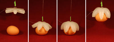


 https://www.calculatorsoup.com/calculators/math/ratios.php